The Right Stuff: Inside the Omega Speedmaster Professional
By: Jack Forster
Part I: Glory Days
On November 21, 1962, President John F. Kennedy met with the (then) Director of NASA - James Webb and Webb's deputy in charge of manned space flight - Brainerd Holmes. The meeting, according to NASA official Robert Seamans Jr. who also attended, was "one of the most dramatic" that he had ever attended and the subject was nothing less than whether the United States would pursue a lunar landing as the primary objective, not only of NASA, but of the entire nation. The meeting, which was recorded on audiotape, shows a President determined to set a course for the moon as quickly as possible, and a Director equally determined to clarify that a moon landing, while politically desirable, should not displace considerations of basic science and safety. Kennedy was aware of the risks, but remained adamant on the matter of beating the Soviets to the moon:
"We've spent half the expenditures, we've wrecked our budget on all these other domestic programs, and the only justification for it, in my opinion, to do it in the pell-mell fashion is because we hope to beat them (the Soviets) and demonstrate that starting behind it (them), as we did by a couple of years, by God, we passed them. I think it would be a helluva thing for us." - JFK, November 21, 1962

Kennedy's determination was understandable. Only a month earlier, during the Cuban Missile Crisis, a nuclear war had been averted through so ticklish a combination of diplomacy and saber rattling that it was only by the narrowest of margins that there was still a Washington D.C. in which to debate the issue at all. It had already been a busy year for the space program - on May 24, Scott Carpenter flew his Aurora 7 Project Mercury spacecraft, and on October 3, Wally Schirra flew Sigma 7, the first Mercury mission to go without a hitch (and during which Schirra revealed his membership in the Ancient and Honorable Order of the Turtles, an Air Force drinking society). Beating the Soviets had long since taken on the dimension of a moral imperative.

On a lighter note, just two days after Schirra's successful flight, another arch-enemy of the Evil Empire had vaulted from the pages of one of Kennedy's favorite authors onto the silver screen; it was the premiere of the first James Bond movie, Dr. No, which starred an obscure Scotsman (Darby O'Gill and the Little People, anybody?) with a pronounced burr and an air of nonchalant menace named Sean Connery, whose rough edges had been smoothed over by director Terence Young, a suave Cambridge graduate and expert in East Asian history who was a former tank commander and a veteran of the disastrous Operation Market Garden around Arnhem in Belgium - fighting yet another Evil Empire (we do seem to go through them, don't we?. Young had been, in fact, shelling Arnhem while the teenaged Audrey Hepburn was living there under Nazi occupation; they would work together years later and joke that Young had been shelling his favorite star without knowing it.)
Connery, as every watch fancier knows, wore a Rolex Submariner for the film, but it was another watch whose career was about to quite literally, take off, that same year - a rather quietly elegant chronograph called the Omega Speedmaster. President Kennedy, of course, couldn't possibly have foreseen all the repercussions of his sometimes heated argument with the temperamental and fractious James Webb, but one consequence was that before the year was out, the search had begun for a watch that would suit NASA's needs for a watch that could be used as a standard issue mission watch for the space program. Wally Schirra had already worn one on Project Mercury's Sigma 7, and as the Apollo program began to gather steam, the way had been paved for the official selection process that was to climax, in 1964, in what aerospace watch enthusiasts think of as The Great Space Race Watch Torture Test, which culminated in the selection of the Speedmaster.
Coincidences and Multiverses
By an interesting coincidence, November 21, 1962 also happens to be my birthday- well, I say coincidence, but connections or their absence are in the mind of the beholder, and while the specific date itself may not matter all that much one way or another, the general time frame has a lot to do with my own fascination with the Speedmaster (at that time still not "Professional," by the way.) When you grow up obsessed with the space program and when months of excited waiting are periodically punctuated by the roar of a rocket leaving the Earth bound for the Moon, you develop something of a fascination with the impedimenta of space travel (those Hasselblad cameras were another early obsession - now as avidly collected and for all I know as expensive or more so than period-Speedmasters. Although, in this brave, new, post-Omegamania world, I'm not so sure.)
I had no idea, of course, while I lay in repose in a bassinet at Norwalk General Hospital that I was lucky to have had a world to be born into at all. As the years have gone by it's become clearer and clearer to historians that it was only by a whisker that nuclear war was averted in October. The physicist and cosmologist Max Tegmark has an interesting theory, which is that if the universe is infinite (which appears to be the case) then the visible universe is only an infinitesimal part of a vast multiverse. One interesting and inevitable consequence, of course, is that you can calculate about how many observable universes away from ours ("Hubble volumes") you'd have to go before running into one in which the particles are arranged the same way they are in ours - where, quite literally, a doppelganger of you is reading these words on a doppelganger-Earth.
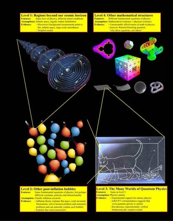
Max Tegmark's hierarchy of parallel universes.
Or not, as well. If in the vast infinitude of space, all possibilities are fulfilled, then somewhere out there is an Earth that never made it past October of 1962 in the calendar fudged together by a Roman emperor and a pope, and which now orbits its uncaring star emitting a trifle more radiation than it should. Life, undoubtedly, still is present on that other Earth (life is pretty stubborn) but I'd bet dollars to donuts I'm not on it. Sometimes it's nice to reflect how unlikely and interesting it is to be here at all.

U-2 reconnaisance photo, Cuba, 1962
I probably would have been a lot less inclined to such dime store philosophizing if it weren't for the space program (to bring this meander slightly untidily back to the subject) and so we return (having conceptually traveled a remarkable number of Hubble volumes and back) to the business of the Omega Speedmaster. After years of being fascinated with the watch but for one reason or another, not owning one, I came to pick one up a few years ago, and in the fullness of time it came to need a service (the truth is it probably needed one when I bought it but damn the torpedoes, full speed ahead, I wanted to wear the darned thing for a while.) With the able aid of a watchmaker friend, I decided to put myself to the task of better grasping the Speedmaster's anatomy.
The funny thing about watches is that like many products of human cleverness - and indeed like many physical systems - understanding them requires a particular kind of intellectual effort (at least it does for me; for all I know most enthusiasts grasp the intricacies of minute repeaters with the ease). Intuition, as I've discovered from studying science a little myself and then from trying to teach it to others, is often a spectacularly lousy guide to understanding physical processes (sometimes it's not, of course, but boy, when your intuition tells you something is true that isn't, look out.) The fact that I'm here at all, to bounce back to the Cuban Missile Crisis and that chancy Fall of 1962, is also due to something interestingly counterintuitive, which is that the proposal that would lead to the resolution of the crisis came from none other than the KGB rezidentura in Washington at the time, a man known as Fomin but who was in fact Alexandre Semyonovich Feklisov, the KGB controller of Klaus Fuchs and Julius Rosenberg. (Fomin happened to have lunch with John Scali of ABC news, and suggested a possible solution to the crisis.)

Alexandre S. Feklisov
Julius Rosenberg was undoubtedly a spy, at least according to Feklisov, but he "didn't understand anything about the atomic bomb" as Feklisov later remarked. So nuclear war was averted by a lunch date between a journalist and a foreign spy working for the very government that menaced the US, who had been the controller of a man and woman convicted and executed of helping that government learn more about the atomic bomb, who had in fact not known anything about it to begin with. One thing you apparently get a lot of in history, in addition to counterintuitive events, is irony. Like the fact that one secret Rosenberg apparently did pass to the Russians was the design for a proximity fuse, a variation of which would be used on the missiles that shot down U2 pilot Rudolph Anderson on the 27 of October, killing him, and deepening the crisis the Feklisov was trying to - well, defuse.

Russian built SA-2 "Guideline" missile, which shot down U-2 pilot Rudolph Anderson over Cuba
The Speedmaster's history - as an amalgamation of counterintuitive principles and otherwise - begins several decades earlier - in 1957 as a matter of fact, the year that Sputnik 1 became the first satellite to orbit the Earth, as long as we are keeping track of coincidences! The Speedmaster wasn't intended, obviously, to be a purpose built aerospace instrument since sending people into space was science fiction at the time - later in '57, Laika the dog became the first astronaut, dying of stress and exposure to elevated temperatures in flight, and putting a watch on an astronaut's wrist was certainly not a guiding principle in the design. The movement went back even further, having started life as project 27 CHRO C12 in the 1940s, the movement was launched in 1942 as a joint project between Omega and Lemania, who supplied it as an ebauche as Lemania cal. 2310. The designers, Albert Piguet and Jacques Reymond, created what many collectors think of as one of the highest developments of the classic, lateral clutch, column wheel controlled chronograph, with a Breguet overcoil hairspring (antimagnetic and with shock protection after 1946, no doubt factors in helping the Speedmaster pass some of NASA's torture tests.) Omega designated the movement cal. 321, and it was used in a variety of chronographs. A testament to its quality is that it has been used over the years as a base movement by Breguet, Patek Philippe, and Vacheron Constantin, among others – sometimes in very fancy dress but like James Bond in a tux (well, Sean Connery in a tux, anyway), hiding real toughness beneath its formal exterior.
So much attention is usually paid by collectors to the history of the movement that the fact that the case didn't spring fully armed from the brow of Zeus is often forgotten; the Speedmaster case was designed, apparently, by one Claude Baillod, about whom posterity has recorded little (at least the posterity I've been able to find.) There are a good few Baillod families in Switzerland, though, who mostly trace their ancestry to the village of Gorgier, which is near St. Aubin in Neuchatel. Many claim descent from the legendary Jacques Baillod who was knighted for defeating the army of the Count of Romont in 1476, receiving the motto: Vires agminis unus habet ("one has the strength of an army") and when Neuchatel joined the Swiss Confederation in 1815, many Baillod family members were watchmakers, some of considerable fame. The Speedmaster case originally had straight lugs, acquiring its bombe lugs in 1966 (pronounced "bomb-bay" – like the city. Or the doors on a bomber for that matter! It was a significant year for bombs of all sorts; the US lost four H-bombs when a B-52 collided with a KC-135 tanker over Spain and US planes began dangerous bombing missions over Hanoi and Haiphong, exposing them to Russian made SAM missiles - those darned proximity fuses again.)
In its original form, in 1957, the Speedmaster had a metal bezel with black numbers engraved on it, was 39 rather than 40mm, and had the so called 'broad arrow' hands; it flirted briefly with alpha hands before settling on the pragmatic baton hands that it still has today (one man's classicism is another's pragmatism - is another's feckless indecision, for that matter). Enthusiasts fanatically describe each and every minor variation in the Speedmaster's dial, case, hands and movement (you know who you are - gadzooks, the tail of the R is below the rest of the letters; the Omega logo is printed, or metal....well, others have done it definitively) but the fact is that these variations are to the Speedmaster enthusiast like the variations in butterfly genitalia are to the lepidopterist - of interest only to the specialist, who as MFK Fisher said of the lover of raw oysters, is warmed by a fanatical fire known only to himself. (You know who you are.)
Fighter Jocks and Torture Tests
By the time Wally Schirra, famous practical joker, honorable Turtle, and bloodied fighter pilot (killed himself a Mig-15 in Korea - flying an F-84, by the way, not the later F-86 Saber; he deserved his Distinguished Flying Cross just for winning a knife fight with the Mig, a far more able dogfighter) had already flown with a Speedmaster, and once John F. Kennedy had, in the seminal meeting of 11/21/62, dispelled any further doubts as to whether or not kicking some dialectic materialist ass was or was not the reason we were in space in the first place, the wheels were turning in their bureaucratic fashion down in Texas, home of NASA's Manned Space Center (later the Lyndon B. Johnson Space Center) to pick a watch that would officially get strapped on any Spam lucky enough to find its patriotic butt in a can headed for a confrontation with the Evil Empire in the High Frontier. Word on the street is that NASA started looking in 1961, when a NASA employee bought the Speedmaster at Corrigan's Jewelry Store in Houston Texas - paying, probably, somewhere around the full retail price, a whopping 82 dollars and fifty cents.
After the Speedmaster's debut spaceflight with Wally Schirra, it traveled into space again - notably with Gordon Cooper, an Eagle Scout and ex-Marine who like many Project Mercury astronauts cut his aviator's teeth on F-84's and Sabres. Cooper wore two watches on Faith 7 , a Speedmaster and a Bulova Accutron, which in addition to having a high-tech aura also had the not inconsiderable PR advantage of being (at the time) an American firm (the Accutron despite repeated attempts never did become an official NASA watch, although Apollo cockpit timers were tuning fork movement Bulova instruments, as it turned out.) Cooper used the Omega to time the retro-rocket firing sequence for re-entry, and the watch performed well, but the real question, which the relatively benign environment of a pressurized and heated capsule interior could not answer, was how well the Speedmaster (or other candidate watches for that matter) would serve not only inside but also outside a spacecraft. Not only that, since whatever watch NASA ended up choosing would also have to be able to function as a backup timing device for critical events like timing maneuvering burns, the assumption was that it might be exposed to the type of environment found in a spacecraft during a catastrophic or potentially crippling equipment failure - sudden increases or decreases in temperature, sudden loss of cabin pressure, venting of toxic combustion products into the cabin atmosphere, and so on. Nobody at the time probably thought there was, realistically, too much of a chance of such a thing happening, but there are times when you're awfully, awfully glad that someone somewhere in the decision making chain of events said to themselves, "better safe than sorry," and making sure that the astronaut's chronograph could tolerate some abuse later turned out to have been a very good idea.
So what did NASA do to the poor chronographs they selected? Well, they baked them (up to 200 degrees Fahrenheit) they froze them (to zero degrees Fahrenheit) they soaked them (95% humidity steambath) they oxidized them (pure O atmosphere- that's right, boys and girls, pure oxygen is very reactive and will break chemical compounds down - why do you think antioxidants are good for you?) they jolted them (six 40-g decelerations, in six different directions. They should have printed, "maladjusted in six positions" on them) and simulated a sustained seven and a quarter g takeoff; they decompressed them (hard vacuum, and then for good measure they baked them again while they were at it; ninety minutes of both at up to 200 degrees Fahrenheit again). Just for grins, they vibrated them at up to 2000 Hz and then, for some reason, they blasted them with sound at 130 db (about as loud as the front row at a very, very loud rock concert. Hey, it was the sixties.)

Take that, JLC Master Control tests.
"It Dawned On Me That We Were In Serious Trouble."
Now, lest any of this strike y'all as excessive, let's bear in mind that Space is Not A Nice Place. In fact, life is hard put to it to survive for very long - no atmosphere to breathe, or to moderate temperatures; enough radiation to make every chromosome in every cell in your body curl up and cry for its momma; blood and body fluids start to boil in the vacuum; and to get there, you basically have to strap yourself into a flying bomb. Rockets, bluntly put, would more than anything else like to blow up, and riding one out of the Earth's atmosphere and gravity well may be great to break up the monotony, but it's not necessarily something you would want to do every day. And the Speedmaster was going to be riding the then-under-development Saturn V, the magna mater of all rockets: a three stage, liquid fueled monster that was 363 feet high and 33 feet in diameter. There really is no way to grasp what a Saturn V launch must have been like if you weren't there; the five main first stage engines generated 7.5 milliion pounds of thrust and created a man-made earthquake picked up by seismographs all across the Southeast USA. Maybe shaking the watches and blasting them with high decibel sound wasn't such a bad idea after all.
March 1, 1965, was the day they finally finished running the candidate watches through their little horological purgatory. It seems like a kind of a long time to take to shake 'n' bake a Rolex, an Omega, and a Longines Wittnauer (the three candidate watches) but maybe they were just being thorough (How was your day at work dear? –Oh, you know, the usual, stared at watches in the oven all day. Again. Where's the Chivas Regal?) and the other two watches both failed (the Longines popped its crystal on two occasions; the Rolex stopped twice from humidity and once during the high temperature test, when the seconds hand warped, binding against the other hands. The Speedmaster passed but not without a bloody nose; the luminescent material on the dial was destroyed, and it gained and lost considerable time during various portions of the test. But it survived.
The Speedmaster's chance to really shine, of course, happened because some clumsy duffer whose name has been lost to history dropped one of the Command and Service module's liquid oxygen tank two inches. That was the immediate cause - the pipes inside the tank that directed oxygen flow were damaged, and the problem wasn't discovered until close to launch. With the damaged pipes inside the only way to empty the tank before refilling it for the mission was to run the heaters at the highest temperature; only 80 degrees Fahrenheit, but the real issue was that this meant a steady 65 volt current flow through thermostats only meant to handle 28 volts (the thermostats were supposed to have been upgraded from 28 to 65 volts but the engineers at Beechcraft, a Saturn V subcontractor, had overlooked them when upgrading the tank.) The best guess is that the excess voltage fused the thermostats, rendering them inoperable and allowing temperatures inside the tank to get so high that the insulation on the wires melted, leaving them exposed - and the wires were inside the tank.

Apollo XIII Prime Crew: Haise, Lovell, Mattingly (l-r) wearing their Speedmasters. Behind them, their spacecraft on the launch pad –the defective oxygen tank has aleady been installed.
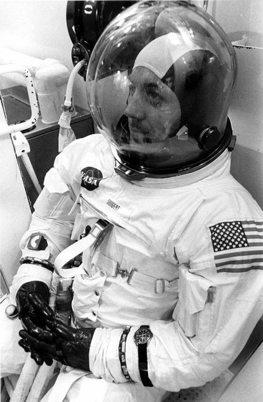
Jack Swigert, launch day. The Speedmaster that timed their 14 second mid-course correction burn is on his wrist.
At Apollo XIII mission time 02 07 52 58, just after a TV broadcast that none of the networks carried because spaceflight had become 'run of the mill' (sic transit gloria!) a 'cryo tank stir' procedure was called for by ground control; this consisted of briefly running fans inside the tank to circulate the liquid oxygen - but the wires going to the fans had no insulation left on them. They short circuited, producing sparks, and an explosion ensued that was so powerful that it blasted a hole in the side of the Command Module that left a hole - well, to paraphrase Earnest Hemingway, was big enough to drive a car through if it was a small car and you wanted to drive it there. At mission time 02 07 55 20, the most famously misquoted line in all of aerospace history was spoken by an individual identified in the mission transcript as 'CDR' – Commander James A. Lovell: I believe we've had a problem here. (The transcript identifies the speaker as Lovell, but the actual tape seems to clearly indicate that the famous words were spoken by CMP - Command Module Pilot Jack Swigert.) CapComm -ground control- responds, This is Houston. Say again please. This time, Lovell answers, Houston , we've had a problem. We have a main bus B undervolt (loss of power.)
It would be presumptuous at this point to do anything more than quote the words of Commander Lovell:
"I guess it's kind of interesting to know what the feelings of the crew are when something like this happens. When you first hear this explosion or bang ... you don't know what it is. We've had similar sounds in the spacecraft before that were for nothing. ... and then I looked out the window and saw this venting ... my concern was increasing all the time. It went from 'I wonder what this is going to do to the landing' to 'I wonder if we can get back home again' ... and when I looked up and saw both oxygen pressures ... one actually at zero and the other one going down ... it dawned on me that we were in serious trouble."

View of the damage to the CSM –taken just prior to re-entry. An entire panel has been blown out, to the right.
The subsequent dialogue, and actual tapes of the exchange, sound surprisingly calm but the flight surgeon's data telemetry showed that the astronaut's pulse rates were skyrocketing. With no oxygen to run the fuel cells, the astronauts were forced to use the LM - the Lunar Module - to which the Command Module was docked, as a lifeboat, and the loss of oxygen for the fuel cells meant that every scrap of battery power in the LM had to be conserved, and that meant turning off every piece of equipment with an on/off switch - including the cockpit timers and the navigation computer. The Speedmaster, suddenly, went from being a footnote in the mission manifest - Item no. A202, Part. No. SEB121000039-02, 'chronograph' stored 'on crew' – to being the only way the crew could tell how long they should burn the LM descent engines for
course correction burns (they couldn't use the Command/Service module engine for fear that the explosion had damaged it and firing up might be the last thing they ever did.) The moment of glory, on which Speedmaster fans have been dining out ever since, was on the return leg of the 'free return' trajectory which took the crippled Command/Service Module and LM around the moon and back towards the Earth.

View of the Moon through the Apollo XIII LM window. The powered down CSM can be seen, upper center.
By then, to save power everything on the LM had been shut down, except for minimal life support and communications systems. With no power for the LM navigation computers or cockpit timers, the astronauts had to orient the spacecraft for the 14 second engine burn by lining up the Earth's terminator and the Sun in the LM window - literally flying by eye - and timing the burn was done with Jack Swigert's Speedmaster. (The official burn time was actually 15 seconds but it's often reported as 14 as the procedure was to shut the LM descent engine down manually at 14 seconds.)
So here we are, boys and girls - we're there, in our imagination, where anybody who could listen to a radio, watch a TV, or read a newspaper could put themselves in April of 1970 - ready in our mind's eye to push that little metal button, cue the engine firing and cutoff, and let's imagine further that we can slow time down and see exactly what does go on inside the Speedmaster when you set the chronograph going. . .
Well. . . now hold on a second. Reader, we have a problem. If you're not one of the lucky or canny collectors who happens to have gotten a Speedmaster made before the fall of 1968, then the Speedmaster that sends you back in time to that cold, dark spacecraft lost in the inky cold of space isn't exactly the same one Swigert had on his wrist - the movement's different. In October or November of 1968, the classic column wheel configured cal. 321 was replaced with the cal. 861 - similar to the cal. 321 but importantly, using what's called a shuttle and cam system for coordinating the various parts that make the chronograph start, stop, and reset. (We lost the Breguet overcoil too, sorry to say.) In fact, in 1996, a further alteration making the movement an 18 jewel movement rather than 17, and changing a metal part for a plastic one, summoned into existence the cal. 1861, which is probably what you've got on your wrist. More to the point, it's what I have on mine, so that's what we're going to look at. (The switch in calibers from 321 to 861 occurred in 1968 and Apollo XIII flew in 1970 but most sources seem to agree that the watches used in the Apollo missions were all acquired by March of 1965, when the first Speedmasters were issued to the Gemini crews.)
But don't let that discourage you too much. Memory and nostalgia after all are not born of the exercise of reason, and if it takes a tiny bit of creative license to make us feel like we're using the same watch to time dryer loads and parking meters that Swigert used to keep the hopes of a nation alive and bring himself and his comrades back home, it's not the deadliest horological sin we could commit. Besides, as we'll see, while cal. 861/1861 may not be a Moonwatch in the narrowest sense, we can take consolation in knowing that it's still a space watch.
But enough pedantry - return with us now, to those thrilling days of yesteryear (any Lone Ranger fans out there?), and let's see what makes the legend tick:
The Right Stuff: Inside the Omega Speedmaster Professional
By: Jack Forster
Part II: Anatomy of a Legend.
Like many watches that have a rich cultural as well as horological history (the Rolex Submariner springs to mind) it's very hard to actually see the Speedmaster as a watch rather than as a point of entry into the legacy of manned space flight which it represents.
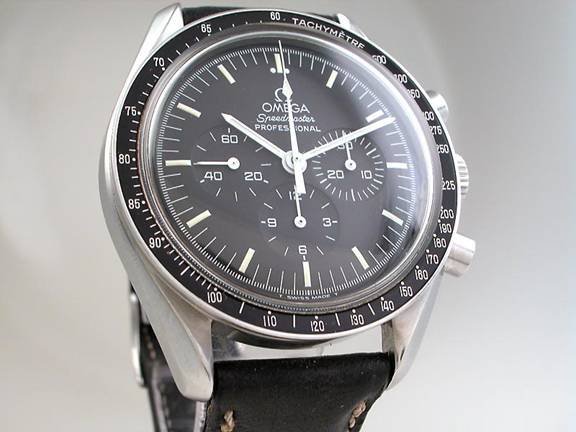
But a watch it is. Our particular Speedmaster , sold to its original owner in 1999, is the most basic model currently available – with largely the same dial that it had in 1970, when Jack Swigert was staring at the dial of his in the chilly, dark, cramped cockpit of the Lunar Module, waiting to count down the 14 seconds of engine firing that would correct their trajectory so as to keep them in their (very narrow) entry corridor. The case of the Speedmaster, with the bombe lugs and at 40mm in diameter, was a large watch for its time but nowadays it seems positively gracile. An eye jaundiced by overmuch consumption of 45mm and larger cases can hardly believe that such a modest looking device was for many years theastronaut's watch of choice (the Russian cosmonauts were fond of them as well) – one just expects something, well, moremacho . However, the Speedmaster was made to a different standard of aesthetics, and even today, the size of the case and the unnecessarily decorative twist to the lugs give the eye an immediately pleasant impression. In its modest way, the case is even beautiful, sexy – not a bad thing, frankly, in a high stress flight environment; the voice used in modern jet fighters for warning recordings is seductively female (pilots have nicknamed it Bitching Betty – "Pull up, Pull up. Dear." )
It may not have the garish flash of many a more recent watch but there is something to be said for its lean, practical, enticing lines. Why Miss Jones, without your glasses. . . .

Speaking of pretty faces, let's talk about the dial. The balance and proportions of each element are so close to perfect as to run the risk of essentially being invisible as such. The tri-compax arrangement of the subdials is perfectly offset by the Omega logo, and, in three different descending fonts, the words Omega Speedmaster Professional , forming a triangle whose lines, when extended, exactly intersect the center of the two lateral subdials. The diameter of the subdials themselves is perfectly inscribed within an imaginary circle formed by the inner edges of the luminous hour indexes; the stick hands are perfectly legible, wide enough to be easily visible but not so massive as to obscure the view of the subdials, and the chronograph seconds hand has a distinguishing arrowhead shaped element, beginning about halfway along its length, which sits, when the chronograph is zeroed, neatly, perfectly, within the Greek letter Omega at the top of the dial. The base of the arrowhead perfectly lines up with the outer edge of the circular base of each of the chronograph hands as well, which can be observed by stopping the chronograph at 15 seconds. The charcoal matte black dial sets off the glossy metallic black of the tachymeter ring, and the slightly domed, Hesalite (acrylic) crystal gives the entire watch an approachable tactility – one or two Martinis (vodka, shaken, not stirred!) and Miss Jones just might let her hair down a little.
It's worth noticing that these nearly perfect proportions are the result of the size of the movement and the size of the case being in harmony – the tendency for modern watches to get so big they look like something from the Acme factory rather than a watch manufacturer has resulted in the notorious "cross-eyed chronograph" syndrome, where the subdials are crowded together disproportionately close to the center of the dial, making the watch as a whole look slightly ridiculous – thehorological equivalent of Spinal Tap stuffing socks down their trousers. Such self-parody is beneath the Speedmaster. One is reminded of James Bond's comment about an American sports car compared to his beloved 1954 Bentley R-Type: That sort of hot rod job's alright for kids who can't afford a real car.
The Works: Caliber 1861
As we've already noted, in 1968, the original cal. 321 was replaced with caliber 861, seen here in all its rose gold glory:
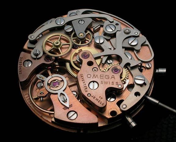
In 1996, the rhodium plated caliber 1861 replaced caliber 861. Unscrewing the caseback (proudly emblazoned with the words "Flight Qualified by NASA for All Manned Space Missions" and "The First Watch Worn on the Moon") reveals a grey antimagnetic dust cover and a solid metal spacer ring – not especially thick, as the Speedmaster and its movement are a good fit.

Aside from the obvious change in finish, note that an additional jewel has raised the count to 18 and that, just above the central chronograph wheel, a plastic brake has replaced the metal brake found in caliber 861. The display back version of the Moonwatch has retained the metal brake and sports a more elaborate finish in general; however mechanically it is otherwise identical to its less decorated sibling.
The first impression one has on examining cal. 1861 is of an overbuilt, solidly constructed piece of equipment designed to pragmatically and practically fulfill the job of timing intervals of elapsed time. There is nothing that strikes one as a superfluous complexity; there are no awkwardly arranged bits that speak to a module added to what started life as a time only movement; no bridge for a nonexistent rotor; and the general thickness and solidity of every part – plates, bridges, wheels and springs – makes one feel assured that here's a piece of machinery designed and refined from the ground up toget the job done .
The Power Train
In disassembling the watch, the first order of business is to remove the chronograph bridge and chronograph mechanism; stripping off the top layer of machinery on the plate leaves us with the power train exposed. Since our main point of interest is working our way through how this type of chronograph works, we'll start by looking first at the power train and then moving on to the chronograph mechanism itself.

With the chronograph mechanism removed, we can see that the construction of caliber 1861 is actually a ¾ plate layout! The exposed top plate allows us to observe the large balance, smaller cock for the escape wheel at the 8 o'clock position, and the jewels for the escape, third, and fourth wheels. Notice also that the train is a 15-jewel train – the two additional jewels in the chronograph bridge raise the count to 17, and in cal. 1861 an additional jewel for the pivot of the chronograph coupling wheel makes it 18 jewels in all. The orientation of the movement is exactly like that of a one hundred and fifty year old pocket watch: the winding crown, if we stop and imagine it in the 12:00 position, puts the fourth wheel arbor at the 6:00 position, right where the seconds subdial would be on a pocket watch – and indeed, in the Speedmaster Professional, the seconds hand runs in a subdial opposite the crown, attached directly to the extended arbor of the fourth wheel. A machine applied striping and smoothly finished edges devoid of beveling or any other unnecessary adornment completes the picture. Removing the ¾ plate (well, all right, the train bridge):

exposes the train itself. Again, no surprises here – just good, solid work; with the usual arrangement – mainspring barrel geared to the large center wheel (remember, during running, the mainspring barrel itself is rotating, whereas in winding the barrel is stationary and the barrel arbor rotates to wind the mainspring, turned by the crown wheel) which then turns the third, fourth, and escape wheels. The extended pivot for the gear that will drive the central seconds counter for the chronograph – the so called "driving wheel," can be seen on the fourth wheel. Come to think of it, gussy this movement up with some Geneva stripes and beveled edges, and maybe move the crown and you'd have a pretty darned nice ¾ plate "Saxon" style movement. Good size for a modern, slightly big hand-wound watch. . . . no, no, perish the thought!
The Balance and Escapement
The lever escapement and 15 tooth escape wheel interact with a large diameter balance, vibrating at 21,600 vph , and in general exhibit the same pragmatic, efficient finish as the rest of the train:


(This balance is actually from a Cal. 861; note the blued hairspring.)
The hairspring is a flat Nivarox hairspring (changed over from the Breguetovercoil in cal. 321 in 1968) and the balance is very typical of watches of this era – kept somewhat light, to reduce the risk of damage to the balance pivots when the watch experiences a shock, but not so light as to undesirably reduce the moment of inertia. Like all mechanical solutions a compromise but a good one –the basic idea is to – well, strike a balance. (Seiko automatic chronographs, such as calibers 6139 and 6138, which were designed and sold starting in 1969, have very similar balances.) The eccentric fine regulator and nicely done curb pins on the regulator sweep complete the picture of a balance and escapement designed to hold a stable rate and once adjusted and regulated, resist shock.
Well, that's the heart of the watch – but this is after all a chronograph. At this stage a useful thing to bear in mind is that servicing and adjusting a chronograph carries some interesting challenges along with it. The basic problem with any watch is that you want the rate to be as stable as possible, and in order to achieve that goal, the balance amplitude has to stay in the neighborhood of a 'sweet spot' generally agreed to be around 280-290 degrees at full wind in the horizontal positions, which minimizes positional error. Anything getting down to around 180 degrees or less, or conversely 300 degrees or above, is going to amplify positional deviation due to poising errors in the vertical positions. Now the problem with a chronograph is that you have different loads on the train depending on whether the chronograph is switched on or off (one of the selling points of a vertical clutch chronograph, in fact, is that the chronograph wheel is always engaged –it's either turning the seconds totalizer hand or not depending on whether the clutch is engaged or not, but the load's not dramatically different with the chronograph on or off.) An acceptable drop in amplitude is generally thought to be somewhere in the neighborhood of 20 to 30 degrees when the chronograph is switched on, and we can immediately see that with an amplitude of 280 degrees, in a properly adjusted chronograph, switching on the chronograph if the watch is fully wound gets us nowhere near the problem zone. As the watch runs down, of course, amplitude starts to drop- after 24 hours, it's probably somewhere in the ballpark of 200 degrees or so, in the vertical positions – but if you're winding your watch once a day, the chances of running the chronograph for a long enough period of time to notice significant inaccuracy in elapsed time situations are probably nonexistent.
The caveat here is that the chronograph has to be adjusted properly and presumably, serviced regularly, otherwise the degradation of lubricants is eventually going to compromise amplitude enough for inaccuracies over extended elapsed time periods to be noticeable. With that in mind, let's have a look at the chronograph mechanism itself.
Following the sequence of events in the operation of a chronograph is one of the things that make horology, as a hobby, fun. You have to be able to hold several different operations in mind at once since several different things are happening at once. But we can do this. In the immortal words of Apollo Flight Director Gene Krantz (Mr. Failure Is Not An Option), let's work the problem, people.
Basic Concepts In Chronograph Operation
All right now. . . if a picture is worth a thousand words, a moving picture is worth. . . well, more:
OK, let's get ourselves oriented here. We are now looking at what happens during starting, stopping, and reset of the chronograph, if we look at the movement from the back, and upside down relative to how it's usually worn. Notice that the start button in our pictures and in the animation is in the lower position, whereas when the watch is worn, it's in the upper (2:00) position.
Let's get the basic principles in place. We've already seen that under all the confusing looking bits and pieces of the chronograph train, there's a basic, bog-standard gear train leading from a mainspring barrel to an escapement. The trick, in a chronograph, is that power from the train has to somehow be coupled, via some sort of clutch mechanism, from the power train to the chronograph train when the start/stop button is pushed. Then, when the chronograph is stopped, the power train and chronograph train have to be disengaged from each other. Finally, once the elapsed time is read, the reset button has to be pushed, which resets the chronograph hands to zero, ready to time another – well, horse race, parking meter, or LM descent engine burn, as the case may be.
We'll get into the specifics shortly, but for now, notice basically what happens as the chronograph is started and stopped. Pushing in the start/stop button causes a series of levers to move which make the component at the 12:00 position move back and forth – this part, which consists of two cams , one on top of the other, performs the same function as a column wheel does in a more traditionally constructed chronograph. The two cams are made to rotate back and forth through the action of a connecting lever actuated by the start/stop button. As the lobes of the cams rotate, they cause other levers to move, which engage and disengage the chronograph train from the power train.
Finally, observe what happens during reset to zero. Instead of the start/stop pusher being depressed, the reset pusher is depressed. This causes a complex looking lever – the reset hammer – to fall, and the flat striking surfaces of the reset hammers land on the heart pieces of the seconds, minutes, and hour totalizers , causing them to very rapidly rotate into the zero position. The chronograph is now reset and ready to go.
With the basic principles in mind, let's look in detail at each phase of the chronograph's operation.
Starting the Chronograph
Let's take a close look at the sequence of events in starting the chronograph.
When the pusher is depressed, it causes a long L-shaped lever – the operating lever – to move inwards. The tip of the operating lever has a notch cut in it that receives the point of a small part called the shuttle . The point of contact between the operating lever and the shuttle is hard to see in the animation since it's partially hidden by the reset hammer and theoperating lever yoke , which is attached to a strong spring shaped like a backwards letter C that forces it to return to its starting position when pressure is released on the chronograph start/stop pusher.
If we remove the reset hammer, we can clearly see the nose of the six-sided shuttle in its notch on the operating lever, with the operating lever yoke engaged with a pin on the upper surface of the shuttle:

Notice that when the start/stop pusher is depressed, the operating lever moves to the left, pushing the shuttle into the lower cam. This causes both the upper and lower cams to rotate, causing the chronograph to start. The return force of the operating lever yoke's spring then pushes the shuttle, and hence the operating lever back into their "resting" position when pressure's taken off the start/stop pusher (the spring inside the pusher itself causes it to return after being depressed).
Hey, I said we could do it, I didn't say it would be easy. Hang in there! Here's a picture of the shuttle with the reset hammer, the operating lever and the operating lever yoke removed:

Funny looking little gizmo, ain't it? But that's what's coordinating the entire operation of the chronograph- that and the cams on the left that it causes to move. This is what I meant before when I said that a lot of mechanical solutions were non-obvious or counter-intuitive; this is not the kind of thing that would immediately occur to most of us if we set ourselves to the task of figuring out how to make a chronograph! If you're wondering who came up with this system for what is now generally known as a shuttle and cam chronograph, the first patent for a non-column wheel, cam-actuated chronograph (sometimes also referred to as a heart piece limiter chronograph) was by the firm of Landeron, in 1940. The original Landeron patent was for a three-button design, and later designs –including calibers from Venus, Valjoux, and Lemania – employed cam systems, simplified and made more robust than the original Landeron patent. A modern shuttle and cam caliber like the Omega 1861 is the end result of over a hundred years of chronograph design and nearly sixty years of tweaking the design of cam actuated chronographs, and it is reliable and robust, as well as being less expensive to manufacture than a column wheel chronograph caliber.
Anyway, back to starting our chronograph – we've gotten as far as seeing how the start button gets the shuttle to play nice with the cams; let's see what happens next.
First order of business is we have to get power from the fourth wheel – the point of connection between the chronograph train and the power train – to the chronograph train. Let's look at our animation again. If you watch the upper cam closely, you can see it rotate clockwise when the chronograph is started. In rotating clockwise, the lobe on the left lifts the arm of a long lever visible on the upper left side of the animation known as the hour recorder yoke. The hour recorder yoke actually has to do, as the name implies, with the hour recorder, and we're not there yet.
Now, turn your attention to the lower cam. During starting, the lower cam rotates clockwise as well. Look closely and you'll be able to see the shuttle pressing against it from the opposite side. If you observe carefully, you'll be able to see, during starting, a lobe of the lower cam rotating clockwise, moving out of the way of the nose of a lever (underneath and roughly parallel to the hour recorder yoke), unblocking it – this lever is more properly known as the coupling yoke , and it carries on it the coupling wheel.
In the animation, there are three wheels visible on the left and center of the movement. The bronze colored one on the farthest left is mounted on the pivot of the fourth wheel – the watch in the animation isn't actually running but in real life, this wheel, the driving wheel , is constantly turning as the fourth wheel turns once per minute. When the lower cam moves, unblocking the coupling yoke, a small spring (just visible to the far left, under the hour recorder yoke) pushes the coupling yoke to the right . The (silver colored) coupling wheel mounted under the small bridge attached to it goes along for the ride, dropping into position between the driving wheel and the centrally located, brass colored chronograph wheel . At this point – Joy of Joys! – We have connected the power train to the chronograph train, and the central seconds register hand, which is attached to the pivot of the chronograph wheel on the dial side of the movement, at long last starts to turn, ticking down our 14-second burn. . .

Left, the brass colored chronograph driving wheel; middle, the coupling wheel (with its upper pivot in the 18 jewel), and to the right, the chronograph wheel.
In the above picture, you can see two funny looking screws that look like someone shaved off their flanks parallel to the slots. Both are eccentric screws; the one on the lower left adjusts the depth of engagement of the coupling wheel teeth with the driving wheel, and the one in the center right, just between the cams and coupling wheel, can be rotated to control the depthto which the coupling wheel teeth engage the chronograph wheel. Both are critical points of adjustment. If the depth is too shallow, the chronograph wheel won't engage securely with the driving or coupling wheels, and if it's too deep, the gears will actually lock up and not turn at all. Omega recommends that the depth of engagement be equal to two thirds the depth of the teeth of the coupling wheel with the driving wheel and one third the depth of the teeth of the couple wheel with the chronograph wheel, just in case you think you're the only one who has to deal with pain-in-the-neck details at work.

The eccentric for adjusting the coupling wheel depth with the driving wheel.
Now, we said we finally got power to the chronograph, and we did, but the chronograph seconds hand is not going to start turning unless we do something else at the same time . The problem here is that each one of the wheels that turn the chronograph hands – including the chronograph wheel itself, of course – is held in place, when the chronograph has been reset to zero (which is where we're starting from) by the reset hammers. The reset hammers have to be lifted off the heart pieces mounted on the pivots of the wheels for the seconds, minutes, and hour totalizers or the hands won't turn.
Now the reset hammers are designed to more or less instantly snap the chronograph hands back to zero when the chronograph is reset. How this is accomplished is a rather neat trick. Let's look at the chronograph wheel. Mounted on it is a so-called heart piece:

Heart piece on the upper side of the chronograph wheel.
The reset hammer, which is the multi-armed doohickey on the upper right of the animation, has two flat striking surfaces, which, when the hammer falls, drop onto the heart piece. The heart piece is designed (it is a modification of a geometric figure known as a cardioid ) so that no matter where the hammer falls, it will cause the heart piece to rotate until the flat of the hammer rests against the "top" of the heart – a position that corresponds to the zero position for the chronograph seconds hand. And so it is for the hour and minute recording runner hands as well.
That means that to start the chronograph, we have to lift the reset hammers out of the way. Looking again at our animation, we can see that the reset hammer on the movement side has two striking surfaces; one resets the seconds register, and the other the minutes register. Both need to be lifted out of the way for the chronograph to start running Lifting the reset hammer is the job of the upper cam (remember that its other job is to lift the hour recorder yoke, which we haven't talked about yet.) As the upper cam rotates clockwise, the lobe on the right side of the upper cam moves downward and presses on the nose of the reset hammer, lifting it out of the way and allowing the chronograph to run. Simultaneously, the lower cam lifts the white, Delrin blocking lever, which was previously held away from the chronograph wheel by a finger on the reset hammer, but more about that in a bit.
So here's the story so far during start-up:
Upper cam: operates the hour recorder yoke (starting the hour register) and simultaneously lifts the reset hammer off the heart pieces of the seconds and minutes registers (we'll look at the hour register reset hammer shortly)
- Lower cam: receives the shuttle to rotate both the lower and upper cams; also operates the coupling yoke that gets the power flow from the fourth wheel through the driving wheel, via the coupling wheel, to the chronograph wheel while also lifting the blocking lever.
Remember, a key difference between a shuttle and cam chronograph and a column wheel chronograph is that a column wheel rotates continuously in one direction, whereas the cams alternately rotate clockwise and counterclockwise during start, stop, and reset. The lower cam is held in whichever position it's in by a jumper spring, seen here resting in one of the two notches designed to receive it in the lower cam:

Now that we've gotten the chronograph train engaged, and we've gone as far as getting the chronograph wheel turning, let's take a look at the minutes register next.
If we remove the bridge that covers the chronograph wheel, we can see that the chronograph wheel drives the wheel on which the minute register hand is mounted (the minute recording runner ) via an intermediate wheel (the runner intermediate wheel .)

To the left is the chronograph wheel, sandwiched between the heart cam on top, and below, a metal disk that carries a finger that engages with the intermediate wheel once per minute. The chronograph wheel advances with every unlocking of the escapement (in a 21,600 vph movement, that means 6 times per second) but the minute recording runner doesn't run continuously – instead, it jumps forward by one minute increments as the finger on the underside of the chronograph wheel advances the intermediate wheel.
To keep the minute recording runner from simply rotating freely when the reset hammer is lifted off its heart piece, a small jumper and jumper spring, which are affixed to the underside of the chronograph bridge, engage with the teeth of the minute recording runner. Remember, we removed the bridge to get a look at the minute recording runner and its intermediate wheel, so let's take a quick glance at the underside of the chronograph bridge:

Here we can see the minute jumper and its spring. The tension exerted by this spring is yet another ticklish point of adjustment. If the tension on the spring is too great, it will require excessive force transmitted through the chronograph wheel and the intermediate wheel to defeat the spring tension and advance the minute recording runner one tooth. Too little tension and the minute recording runner may bump forwards or backwards if the watch gets a jolt during running. Omega recommends that there be a flexure in the middle of the spring of approximately 0.10 to 0.15 mm with the jumper removed.
One final point, before we turn our attention to the hour register, is to note that the pivot for the chronograph wheel, to which the seconds register hand is attached, runs through the hollow pivot of the center wheel, which we can see if we examine the train again:

To prevent the chronograph wheel from jumping erratically a small tension spring, attached to the train bridge, presses up against the underside of the metal disk on the bottom of the chronograph wheel to secure it in position. The friction spring is visible in the picture of the movement without the chronograph train and can be seen here in close-up:

This friction spring more than any other single component is responsible for the drop in amplitude a conventional chronograph experiences when the chronograph is started. A dry surface lubricant is applied to the fork of the tension spring in some iterations of this movement in order to limit the degree to which friction saps additional power from the train.
In a stepwise fashion, we've seen how depressing the start/stop pusher moves the operating lever and shuttle, causing the cams to rotate. This in turn allows the coupling wheel to drop into place, feeding power to the chronograph wheel and minute recording runner. (And of course, the cams also lift the reset hammer off the heart pieces for the chronograph wheel and minute recording runner in addition to lifting the blocking lever so they're free to turn.)
At this point an alert reading is probably scratching his or her head and wondering, how does power get to the hour recorder? And for that matter, where's the hour recorder at all?
Well, the answer is a little unexpected – you will look in vain for the hour recorder on the top plate side of the movement (the side we've been looking at) because guess what – it ain't there. Unlike the chronograph wheel and minute recording runner, the hour recorder doesn't run off power coming from the fourth wheel – in fact, it's not linked mechanically to the other two at all. The hour recorder, surprise surprise, runs directly off the mainspring barrel, which means that to see how it engages, we're going to have to flip the whole blessed movement over and look at the dial side.
Bet you didn't see that coming.

OK, here is the dial side of the movement.
We can see in this picture what is under the dial of the watch – imagine that we've decased the movement, removed the hands, removed the dial, and now we can see the motion works that drive the hour and minute hands, the keyless works for hand setting and hand winding, the stem, and, most importantly, we can see a bridge covering the mainspring barrel, which is at more or less the entire four to six o'clock position (if we think of the stem as being at three o'clock.) The bit that we want to get turning – the hour recorder runner – can just barely be seen as its edge protrudes out from under the inner edge of the barrel bridge, along with its bushing at six o'clock.
Fortunately for us, we have an animation of the action on the dial side as well:
Click to view image
As with our examination of the top plate action, a few minutes spent getting oriented here will save us a lot of confusion.
Now we have already established that the hour recorder yoke – which, remember, is on the other side of the movement – is lifted up by a lobe of the upper cam during starting. A projection on the underside of the hour recorder yoke passes through the movement from the top plate side to the dial side, and can be seen as a small pin located at nine o'clock in the dial side animation – you can see it moving slightly to the right during startup of the chronograph. As it moves, it presses against theswitch located next to it, which in turn lifts the hour recorder brake – officially known as the hour recorder stop lever – off the edge of the hour recorder, allowing it to start turning.

Here we can clearly see the pin on the underside of the hour recorder yoke, passing through a hole in the movement and pressing against the switch.
Now, the sixty five thousand dollar question is, where's the clutch that connects the hour recorder to the mainspring barrel? The somewhat surprising answer is that there isn't any – at least, nothing like the mechanical clutch that engages the driving wheel with the coupling wheel on the other side of the movement. Instead, a friction fit wheel fitted to the mainspring barrel is constantly engaged with the hour recorder, and it is simply the pressure of the hour recorder stop lever that holds the hour recorder in place and prevents it from turning, even though it "wants to." To get a better idea of how this works let's take off the barrel bridge for an unobstructed view of the barrel and the hour recorder:

In this picture the barrel bridge has been removed, along with the hour recorder stop lever (much less confusing to call it the hour recorder brake but who am I to argue with Omega) and we can see exposed the silver colored hour recorder runner, as well as, gearing to it, a brass colored wheel, the driving pinion. The driving pinion is mounted on the mainspring barrel arbor and is held in place against the barrel by the rounded square shaped spring underneath with the clover leaf cutout, which is known as the friction spring for driving pinion. (Pure poetry, these part names. They sound so much better in German –Friktionsfeder des Mitnehmertriebes, anybody?)

(It should be noted that these two pictures show the barrel from a Cal. 861, note the blued friction coupling for the driving pinion.)
Here, with the barrel removed, we can see the driving pinion in place, with the friction spring underneath, and with the barrel disassembled:

We can see the barrel, barrel cover, arbor, the driving wheel, the friction spring, and the two screws that hold the friction spring in place. The two tongues of the friction spring press down on the top of the dark purplish flange under the driving wheel (beryllium bronze colored in the Cal. 1861), holding it down on the cover plate of the barrel.
Thanks to the downward pressure of the friction spring, if the driving wheel is free to move it will rotate as the barrel rotates, thereby driving the hour recorder –however, the hour recorder stop lever is pressing against the teeth of the hour recorder before the chronograph is started, preventing the driving wheel from turning. As strange as this arrangement might seem at first, it is the general standard design for driving chronograph hour recorders, and in this seven year old watch, the points of contact between the barrel, driving wheel, and friction spring showed no visible wear. Not that there's any particular reason why they would – remember, the mainspring barrel only turns when the watch is running (it's the arbor that turns during hand-winding; the barrel's stationary) and the entire barrel turns maybe four times a day. This is not a high-speed area.
Notice also, by the way, that before starting the chronograph, the chronograph wheel and minute recorder are held in place by the reset hammer; however, the hour recorder is held in place by the hour recorder stop lever, and the reset hammer for the hour recorder comes into action only during actual reset.
So at long last, the final piece of the puzzle falls into place, and we can see how starting the chronograph works:
Chronograph wheel and minute recording runner: reset hammer is lifted to free them to turn; coupling wheel falls into place, allowing power to flow from the driving wheel to the chronograph wheel; chronograph wheel via a finger on its underside drives an intermediate wheel that turns the minute recording runner one increment per minute.
- Hour recording runner: hour recorder yoke lifts the hour recorder stop lever off the teeth of the hour recorder, freeing it to turn thanks to the power flowing to it from the mainspring barrel via the driving wheel. (remember: the barrel is turning, not the arbor, so it's actually the friction of the friction spring against the flange of the driving wheel that transfers power from the barrel to the driving wheel.)
And now, at last, she's off. Swigert at this point very likely had his eyes glued to the dial, and thank goodness, with total unconcern for the drama of the moment and the almost astronomically unlikely sequence of events that produced it, theSpeedmaster was doing its job. The three men, crowded in this narrow space:

with the Rocketdyne built descent engine roaring, executed the maneuver as best they could, despite their misgivings.
"When the ground read out the procedure to us, I just couldn't believe it. I thought I'd never have to use something as way-out as this. And here I was on Apollo 13, using this very same procedure. Because it was a manual burn, we had a three-man operation. Jack would take care of the time. He'd tell us when to light off the engine and when to stop it. Fred handled the pitch maneuver and I handled the roll maneuver and pushed the buttons to start and stop the engine." – James Lovell.
. . . 11, 12, 13, 14, shutdown!
And we're ready for. . .
Stopping the Chronograph
Having just devoted ourselves to diligent study of both the basic chronograph components, and their coordinated operation in starting the chronograph wheel, minute, and hour recording runners, we are now in a position to easily understand the coordinated operation of the functions of stopping and resetting the chronograph.
Returning to the movement side, and contemplating our movement side animation, the action of the chronograph in stopping is clear.
First, let's direct our attention to the shuttle and lower cam. Notice that because the lower cam has rotated clockwise during starting, its relationship to the shuttle has changed. As the start/stop pusher is depressed, and as the operating lever presses home the shuttle, the shuttle now rides against the upper, rather than the lower lobe of the lower cam. This causes the lower cam to rotate back into the position it was in previously (counterclockwise). The immediate effect is that the power flow to the chronograph wheel and minute recorder is interrupted. The coupling wheel travels, on the coupling yoke, out of engagement with the chronograph wheel, which stops turning, and of course no longer causes the minute recorder to turn.
We can also see that the upper cam allows the hour recorder yoke to drop back into its starting position. On the dial side, this has the effect of releasing pressure on the switch, which in turn releases pressure on the tail of the hour recorder stop lever. The spring for the hour recorder stop lever (that's the resort de sabot de bloqueurducompteurd'heures to you, pal) then pushes the hour recorder stop lever back into engagement with the hour recorder, which ceases to turn.
Now a critical point to notice on the dial side, is that the chronograph wheel is not held stationary by the reset hammers when the chronograph is stopped during running. If the reset hammers (which were lifted off the heart pieces to start the chronograph) were allowed to fall into place when the chronograph stopped during running, of course the registers would immediately reset to zero and you wouldn't be able to read the elapsed time.
The problem here is that the reset hammers are lifted out of the way by a lobe on the upper cam (as we already noted) but, when the chronograph is stopped, the upper cam rotates back into its starting position – this should allow the reset hammer to fall. But it can't. The reason is because as the reset hammer is lifted out of the way during starting, a notch on the underside of the reset hammer passes over and then locks on a bolt extending from the reset button. When the chronograph is stopped, but not yet reset, even though the lobe on the upper cam no longer holds the reset hammer in place, it's still kept from falling back on the heart pieces by the reset bolt.

In this picture, we see the pusher for reset on the right, and the bolt that engages with the notch on the reset hammer. Notice that the reset hammer is not actually touching the bolt in this picture – that's because the picture shows the watch during running of the chronograph , and in that state, the reset hammer is held away from the heart pieces by the lobe on the upper cam. However, if we were to push the start/stop button, stopping the chronograph, the upper cam would allow the reset hammer (under the pressure of the reset hammer spring) to start to drop towards the heart pieces – but the bolt would stop it.
There is another critical difference between the stopped and reset state, and the stopped while running state – that is that the chronograph wheel, which must be held in a fixed position while the elapsed time is read off, is held in place by the one plastic component in the watch: the blocking lever , also often referred to as the chronograph brake.

In this picture, the chronograph is running. Note that the reset hammer is lifted, and the cam has rotated counterclockwise allowing the coupling wheel to engage the chronograph wheel. In the upper center of the picture the shuttle is being held in place, away from the lower cam, by the operating lever yoke and its spring (not visible). Now if you examine the animation again, you will notice something important, which is that in the stopped and reset state, with the hammer dropped into position, the projection on the arm of the reset hammer for the chronograph holds the plastic stop lever off the chronograph wheel. Equally importantly, when the chronograph is stopped during running, the reset hammer does not fall back into place; this allows the plastic stop lever, as the lower cam rotates clockwise, to fall into place (pushed by its spring) and hold the chronograph wheel in the "elapsed time" position. Re-starting the chronograph causes the lower cam to rotate counterclockwise again, lifting the stop lever off the chronograph wheel and allowing it to run.
In essence, the chronograph mechanism is a kind of simple, but quite clever computer. There are two possible inputs: depressing the start/stop pusher (A input) and depressing the restart button (B input.) Call the initial state (chronograph stopped, hands reset to zero) state a.
If state a , and input A, then state b (chronograph starts.)
If state a, and input B, then state a (no change – you can't start the chronograph with the reset button.)
If state b, and input A, then state c – and this is the clever part; you would expect a return to the ground state, but instead athird state is achieved, the "stopped during running" state. As we have seen, this state is different from the stopped and reset state – the reset hammers are clear of the heart pieces (on the dial side) instead of pressing on them, and the reset hammers are also locked in place so that only input B (pressing the reset button) when in state c will allow them to fall . In addition, the plastic chronograph stop lever is free to fall into position and stop the chronograph wheel in state c but not in state a.
Thus, through the use of only two inputs, the chronograph is capable of remembering it's previous state, and calculating what the next state should be based on adding together the current state, and input. Understanding the nature of this problem gives us a much better appreciation for the great ingenuity required to solve it.
Reset To Zero
The reset to zero action, on the dial side, is now easy to understand, if we remember the state of the chronograph during the "stopped during running" state. Pressing the reset button causes the bolt holding the reset hammers above the heart pieces to unlock the reset hammers. The reset hammers fall, striking the heart pieces on the chronograph wheel and the minute recorder, and both more or less instantly return to zero.
Notice that in falling, a flange on the reset hammer also lifts the plastic chronograph stop lever off the chronograph wheel. This is essential in order for the chronograph wheel to be able to turn and rotate back to its start position. The minute recorder, held in place only by the spring jumper, also rotates back into the start position.
On the dial side, reset of the hour recorder is relatively straightforward. Depressing the reset button, in addition to operating the bolt that frees the reset hammer for the chronograph wheel and minute recording runner, also presses the tail of the hour hammer directly, causing it to pivot and fall into position on the heart piece of the hour recorder runner. Notice, in the dial side animation, that as it falls home onto the hour recorder runner heart piece, the reset hammer also lifts the hour recorder stop lever free of the hour recorder runner, allowing it to rotate into the start position. As its spring lifts the hour hammer back off the hour recorder runner, the hour recorder stop lever drops into place to prevent the hour recorder runner from advancing.
The entire chronograph has now been reset, and is ready to time another elapsed event.
We should also note that the reset-to-zero pusher cannot physically be depressed while the chronograph is running. (It canbe depressed after reset to zero but there is no effect. And of course pushing it when the chronograph is in the stopped-while-running state causes the chronograph to reset to zero.) The reason is because while the chronograph is running, the tip of the hour recorder stop lever (on the dial side) rests against a small vertical projection on the hour recorder runner's reset hammer:

Pressure on the reset pusher, remember, forces the hour hammer to fall, but during the running state, the hour recorder stop lever is lifted free of the hour recorder runner and blocks the reset hammer from falling – and therefore the reset pusher from being pushed in.
Owners sometimes wonder if it's possible to damage the watch by pressing the reset button while the chronograph is running – theoretically of course, enough pressure will either shear off the protrusion on the reset hammer or perhaps bend the hour recorder stop lever (and dropping the watch so that the reset pusher hits a hard surface during running may indeed inflict significant damage) but as a considerable amount of force would have to be deliberately exerted in order to defeat the blocking of the hour hammer, it's to be hoped that common sense would warn the experimenting owner that such an application of significant pressure is probably inadvisable.
In the Eye of the Beholder
If form following function is beautiful, then the movement of the Speedmaster is a thing of beauty. In terms of finish, there is very little if anything that could be said to be decorative; most of the embellishments associated with haute horlogerie are resolutely absent. However, it's also true that there are few, if any, signs of inattention or lapses in solid functional finish, and in this six year old watch, the condition of the movement when opened reflects its robustness – there were virtually no signs of wear of any significance at all in the movement, and the only part replaced (which is routine) was the mainspring.
As a mechanism, as a piece of engineering, caliber 1861 represents the culmination of many decades of chronograph evolution. There is virtually nothing left to chance in its operation, design, and execution, and in both the reliability of its action and the burly, utilitarian dimensions of its components, the Speedmaster is a watch clearly designed and intended throughout not to dazzle the eye, but rather to do its job and to do it as well as possible. Even the sometimes derided plastic stop lever for the chronograph wheel is a concession to pragmatism; the plastic's surface properties give it a secure purchase on the small and relatively delicate teeth of the chronograph wheel without any risk whatsoever of damaging them. The Speedmaster has enjoyed a hard earned reputation for toughness for many decades, and that reputation is clearly well deserved.
Part III: Sic Transit Gloria
The Speedmaster , of course, amply repaid the trust put in it by NASA, and performed flawlessly for the crew of Apollo XIII – they ended up splashing down a mere four miles from their target site, which was not only fantastic accuracy considering the circumstances, but also the most accurate splashdown of any manned space mission to date. The Speedmaster was worn on all subsequent Apollo missions, and was, in fact, recertified for cockpit and EVA operations again in 1972.

Post mission debriefing, Houston, 1970. Fred Haise , right, still wears his Speedmaster.
There was political pressure from the Bulova Watch Company at the time to dump the Speedmaster in favor of an American made watch, and Bulova had successfully lobbied the White House to force NASA to adhere to regulations compelling the agency, when possible, to purchase from American suppliers. A total of sixteen watch companies were notified by NASA that they were planning on establishing a list of qualified products for future astronaut watches. Bulova did its level best, submitting specially prepared chronographs for a repetition of the Torture Tests, but when the retesting process was completed in December of 1972, the Bulova chronographs had failed. Dale Myers, Associate Administrator for Manned Space Flight, gave the final word on the subject:
"The special Bulova chronographs purchased by MSC for possible application for Apollo 17 and Skylab, have failed their qualification tests both in humidity and acceleration. I have instructed the Manned Spacecraft Center to take no further action with respect to chronograph testing or other companies' watches. I consider the Bulova watch issue closed."
Well. . . in politics, no issue is ever closed. In 1978, Bulova was at it again , this time enlisting Senator Jacob Javits of New York, who persuaded NASA to once again open a competition for an official astronaut's watch. (By this time, incidentally, Russian cosmonauts were also wearing Speedmasters if they could get their hands on them – during the Apollo Soyuz mission in 1975, both flight crews were wearing Speedmasters.) The recertification process took place once again, and, to quote Alan Nelson's excellent historical study of the Speedmaster:
Once again, the Omega chronograph was superior to the other chronographs tested. The Speedmaster Professional met all environmental requirements, had the highest technical score, and was offered at the lowest price. Therefore, the Omega was accepted for procurement. It is significant to note that this was the identical model, which had been submitted in 1962. The watch was offered to NASA at the cost of $0.01 per watch.
And in 1989, the Soviet Union heaved a collective sigh and made it official –selecting the Speedmaster as the official watch to be supplied to all cosmonauts. That the watch was offered to NASA "at the cost of $0.01 per watch" clearly seems to indicate that NASA purchased watches in addition to the early, 1965 batch of cal. 321 Speedmasters (one certainly hopes so, otherwise Shuttle crews would have been flying with watches rather conspicuously outside the recommended service interval!) It's therefore quite reasonable to acknowledge that while the current Speedmaster with cal. 1861 is not exactly the original Moonwatch, it is still a workhorse instrument repeatedly proven to be able to tolerate the rigors of operation beyond the surly bonds of earth.
Today, of course, with the aging and dangerous Space Shuttle reaching the end of its service life, and with NASA's stock in trade consisting largely of scientific missions to the planets in which incredibly sophisticated robot probes have taken the place of manned space flight (largely a sensible decision both from a cost and safety standpoint, it must be admitted) theSpeedmaster , too, has largely been superseded. The mechanical Speedmaster Professional has been supplanted by the X-33, an up to date quartz mechanical/analog watch designed, unlike the Speedmaster, to function specifically in aerospace activities (it includes a whole host of features included at the behest of the aviators and astronauts who participated in its design, including a multi-day mission timer, and alarms loud enough to actually be useful.) Astronauts and serious military aviators today generally rely on quartz digitals, including the other two watches (in addition to the Speedmaster and X-33) that are officially flight qualified by NASA, the Timex Ironman and the Casio G-Shock.
But for me, and for others of my generation, the Speedmaster remains a kind of horological equivalent to Proust'sMadeleine, a trigger for a cascade of memories and aspirations both personal and national, which are no less sweet for having largely given way to the pressures of changing time and age. Like so many who grew up during those early days of the space race, I wanted more than anything else to be an astronaut, and though that ambition has long since fallen away, theSpeedmaster's honest construction, rich history, and personal meaning makes it for me, and for many of my generation, the ultimate touchstone of horological authenticity. Let other watches dress themselves in the tawdry robes of borrowed or inauthentic history; the Speedmaster has been there, done that, and lived (sometimes by the skin of its teeth) to tell the tale. Age cannot wither nor custom stale her allure, which is more than you can say for most of her owners, so as theSpeedmaster turns 50, let us all salute her, and wish her another 50 years of reminding us of where we've been, and where, perhaps, we might someday go again.
Sources:
The Moon Watch: The First and only Watch Worn on the Moon, published by Omega SA
Apollo Lunar Surface Journal
W. David Compton, Where No Man Has Gone Before: A History of Apollo Lunar Exploration Missions (Washington, D.C.: NASA SP-4214, 1989)
Chuck Maddox's Speedmaster Articles (http://home.xnet.com/~cmaddox/cm3articles.html)
Club Speedmaster (http://www.clubspeedmaster.com/space/tests.htm)
"The Moon Watch: A History of the Omega Speedmaster Professional" NAWCC Bulletin, Feb. 1993, Alan A. Nelson
JFK and the Space Race, Marc Selverstone , Miller Center of Public Affairs of the University of Virginia (http://tapes.millercenter.virginia.edu/exhibits/space/)
Antiquorum Archives and Omegamania Catalogue
Max Tegmark , "Parallel Universes," Scientific American May 2004
Jack Forster has asserted his right to be identified as the author of this work.
Copyright assigned to PuristSPro.com , May 2007. All rights reserved .
No comments:
Post a Comment